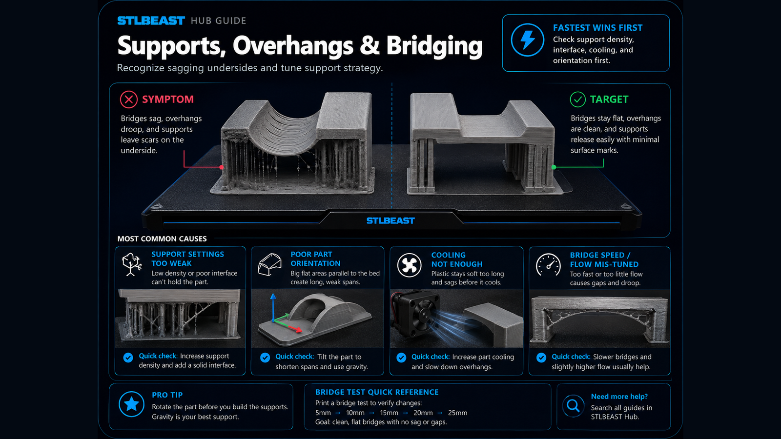
A detailed STLBEAST repair guide to make narrow geometry printable without distorting the design. Learn how to recognize the symptom, rank the likely causes, apply safe fixes in order, verify the result, and prevent the failure from returning.
Fast answer
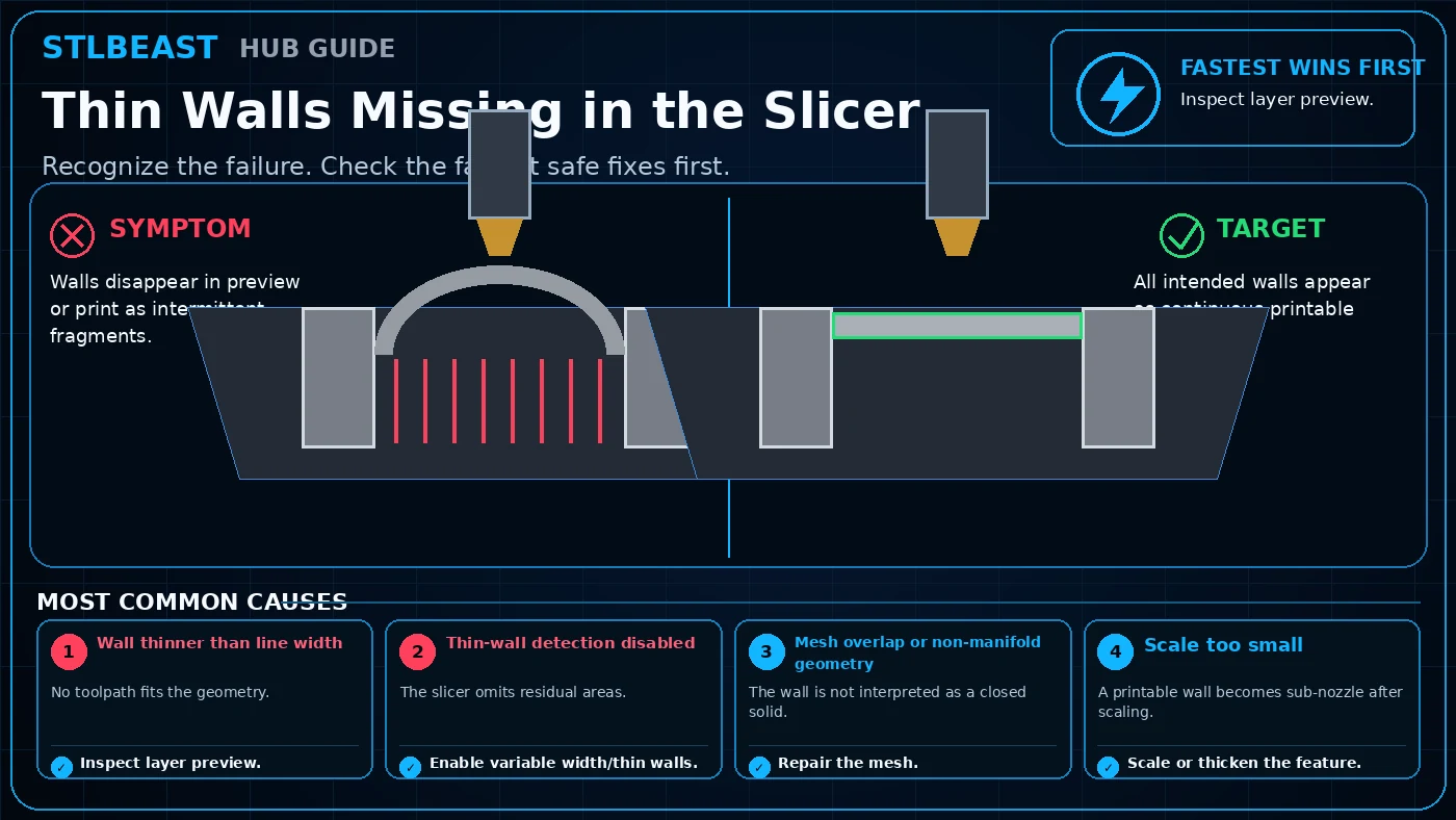
Start with inspect layer preview, then enable variable width/thin walls. Confirm the result with a short representative test before changing additional settings.
Inspect mesh overlap or non-manifold geometry. Repair the mesh.
Rule out scale too small. Scale or thicken the feature.
Change only the single setting or hardware condition supported by the evidence, then run a small test that reproduces the original failure.
Compare the test against the target condition, record the successful value, and save it in a printer/material profile before repeating the full print.
Safety and accuracyStay within the printer, material, resin, hotend, build-surface, electrical, ventilation, and personal-protection limits published by the manufacturers. Stop immediately for heater errors, smoke, electrical damage, severe binding, or resin exposure.
Fast decision path
1If you see evidence of wall thinner than line width
No toolpath fits the geometry. Confirm it with the smallest safe test before continuing.
2If you see evidence of thin-wall detection disabled
The slicer omits residual areas. Confirm it with the smallest safe test before continuing.
3If you see evidence of mesh overlap or non-manifold geometry
The wall is not interpreted as a closed solid. Confirm it with the smallest safe test before continuing.
Settings to review
Setting
How to use it
Support threshold
Support only geometry that cannot bridge or overhang cleanly.
Interface density
Use enough continuous contact to hold the underside.
Contact Z distance
Set in layer-height increments and test removal.
Orientation
Often provides a larger quality gain than adding more support.
Material notes
PLA
Good cooling makes support gaps and bridges easier.
PETG
Can fuse to supports; use cautious interface and separation settings.
TPU
Flexible supports can be difficult to remove and may need redesign.
Resin
Use island, suction, orientation, and support-tip logic rather than FDM gaps.
Printer context
Bedslinger
Check bed seating, gantry alignment, belts, eccentric wheels, and first-layer consistency across the plate.
CoreXY
Start from the official machine profile; inspect belt balance, input shaping, flow, pressure advance, and chamber conditions.
Delta
Confirm delta calibration, tower movement, belt tension, effector stability, and full-bed mapping.
Resin / SLA
Use resin-specific exposure, lift, support, temperature, wash, cure, and personal-protection procedures.
Where to look in the slicer
OrcaSlicer / Bambu Studio
Process → Quality, Strength, Speed, Support and Filament settings; use calibration tools for temperature, flow and pressure advance.
PrusaSlicer
Print Settings, Filament Settings and Printer Settings; inspect the sliced preview and layer slider before export.
Cura / Creality Print
Quality, Walls, Top/Bottom, Material, Speed, Travel, Cooling, Support and Build Plate Adhesion.
Resin slicers
Printer/resin profile, exposure, lift/retract, support contact, raft and hollow/drain settings.
How to verify the fix
All intended walls appear as continuous printable paths.
The same test succeeds at least twice without a new artifact appearing.
No safety warning, unusual noise, heater error, binding, or material damage is introduced by the change.
The successful values are recorded with printer, nozzle, material, slicer, and date.
Prevent it next time
Keep a known-good baseline profile and duplicate it before experimenting.
Inspect the relevant mechanical or material condition during routine maintenance instead of waiting for a failed print.
Change one variable at a time and use short calibration objects to avoid wasting long prints.
Re-check the result after nozzle, build plate, hotend, firmware, slicer, or material changes.
Printer Settings preview
Useful sample now. Full personalized profile for members.
Every visitor can use the guide and receive a practical sample. Members unlock the complete printer/material profile, exact adjustment order, copy/export controls, saved Profile Vault history, and deeper AI Doctor linkage.
Support thresholdSupport only geometry that cannot bridge or overhang cleanly.
Interface densityUse enough continuous contact to hold the underside.
What should I check first for thin walls missing in the slicer?
Inspect layer preview. It is the fastest low-risk check and often separates a profile issue from a hardware or material issue.
Can wall thinner than line width cause this problem?
No toolpath fits the geometry. Confirm it with the smallest safe test before changing unrelated settings.
Should I change several settings at once?
No. Multiple simultaneous changes hide the real cause and make the successful setup difficult to reproduce.
When should I stop troubleshooting and inspect hardware?
Stop if you see heater errors, electrical damage, binding, smoke, unusual heat, severe collisions, leaking resin, or any condition outside the manufacturer safety guidance.
STLBEAST ecosystemFix and learn on Hub. Build with validated files on STLBEAST.com.
Disclosure: Hub.STLBEAST is an educational resource. Some recommended-tool links may be affiliate links, including Amazon Associate links, and STLBEAST may earn from qualifying purchases at no extra cost to you.