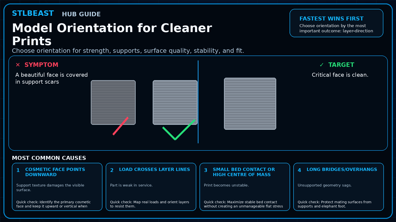
Improve surfaces above supports, reduce pitting, and protect visible detail.
Fast answer
Prioritize orientation and interface design. A perfectly smooth downward face is difficult with same-material supports, so move cosmetic surfaces away from support whenever possible.
Use the visual comparison first, then follow the ordered checks below.
Before you change settings
Confirm the exact printer, material, nozzle or resin, slicer, and recent hardware changes.
Photograph the failure before removing the print so the evidence is not lost.
Return extreme overrides to a known profile and change one variable at a time.
Use a small calibration object or representative model section before repeating a long print.
What it looks like
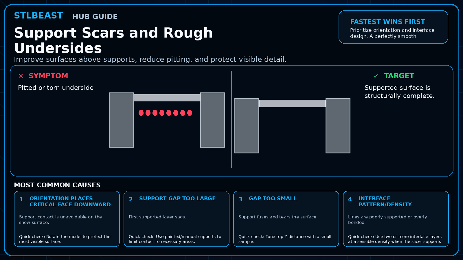
Pitted or torn underside
Visible support grid imprinted into surface
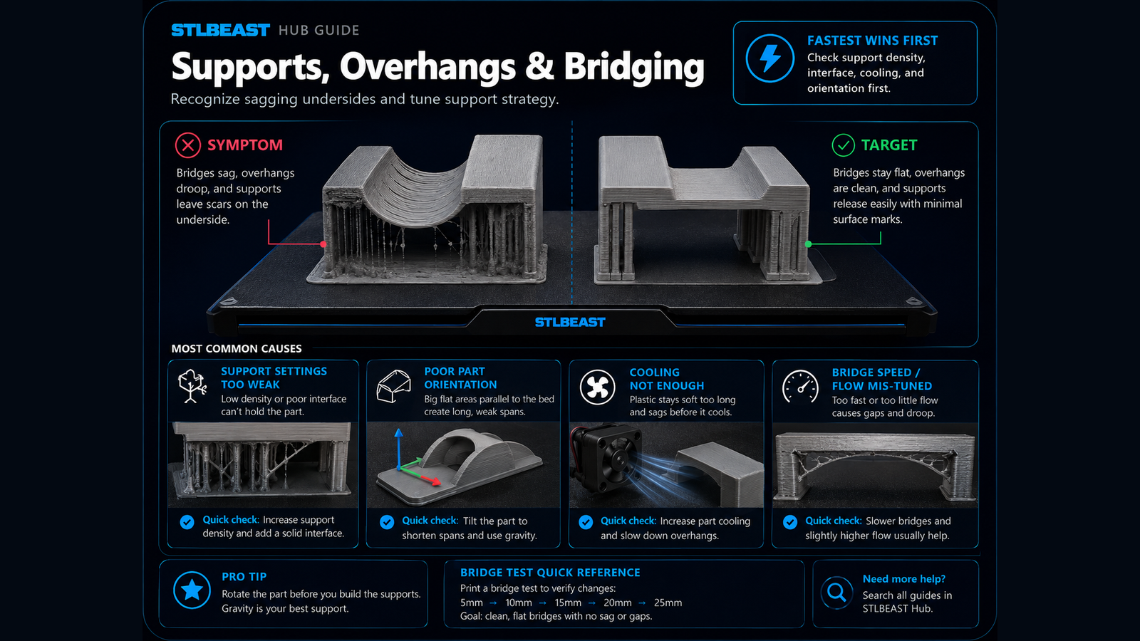
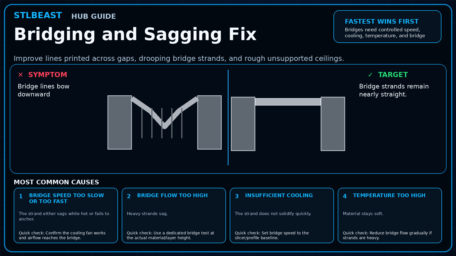
Drooping lines above support
Scars only on one decorative face
Most likely causes
Orientation places critical face downwardSupport contact is unavoidable on the show surface.
Support gap too largeFirst supported layer sags.
Gap too smallSupport fuses and tears the surface.
Interface pattern/density mismatchLines are poorly supported or overly bonded.
Cooling/temperature imbalanceThe bridge layer cannot hold shape.
Repair sequence
Work from top to bottom. Stop when the failure is resolved, verify it with a small test, and record the successful setup.
Rotate the model to protect the most visible surface.
Use painted/manual supports to limit contact to necessary areas.
Tune top Z distance with a small sample.
Use two or more interface layers at a sensible density when the slicer supports it.
Slow the first layer above support.
Tune cooling and bridge flow for the material.
Consider splitting and joining the model.
Safety and accuracyChange one variable at a time and keep every adjustment inside the printer, hotend, build-surface, and filament manufacturer limits.
Fast decision path
1If you see evidence of orientation places critical face downward
Support contact is unavoidable on the show surface. Confirm it with the smallest safe test before continuing.
2If you see evidence of support gap too large
First supported layer sags. Confirm it with the smallest safe test before continuing.
3If you see evidence of gap too small
Support fuses and tears the surface. Confirm it with the smallest safe test before continuing.
Settings to review
Setting
How to use it
Interface pattern
Choose a consistent pattern supporting the first model layer.
First layer above support
Slow and cool appropriately.
XY separation
Prevents side walls from bonding to support.
Material notes
PETG
Sticky interfaces may need extra separation.
ABS/ASA
Lower fan means orientation and enclosure stability matter more.
Printer context
Bedslinger
Check bed seating, gantry alignment, belts, eccentric wheels, and first-layer consistency across the plate.
CoreXY
Start from the official machine profile; inspect belt balance, input shaping, flow, pressure advance, and chamber conditions.
Delta
Confirm delta calibration, tower movement, belt tension, effector stability, and full-bed mapping.
Resin / SLA
Use resin-specific exposure, lift, support, temperature, wash, cure, and personal-protection procedures.
Where to look in the slicer
OrcaSlicer / Bambu Studio
Process → Quality, Strength, Speed, Support and Filament settings; use calibration tools for temperature, flow and pressure advance.
PrusaSlicer
Print Settings, Filament Settings and Printer Settings; inspect the sliced preview and layer slider before export.
Cura / Creality Print
Quality, Walls, Top/Bottom, Material, Speed, Travel, Cooling, Support and Build Plate Adhesion.
Resin slicers
Printer/resin profile, exposure, lift/retract, support contact, raft and hollow/drain settings.
How to verify the fix
Supported surface is structurally complete.
Scars are limited to hidden areas.
Support removes without tearing.
Dimensional faces remain accurate.
Prevent it next time
Design chamfers/arches instead of flat unsupported ceilings.
Plan split lines intentionally.
Use sacrificial contact points.
Save support presets by material.
Printer Settings preview
Useful sample now. Full personalized profile for members.
Every visitor can use the guide and receive a practical sample. Members unlock the complete printer/material profile, exact adjustment order, copy/export controls, saved Profile Vault history, and deeper AI Doctor linkage.
Interface patternChoose a consistent pattern supporting the first model layer.
First layer above supportSlow and cool appropriately.
STLBEAST ecosystemFix and learn on Hub. Build with validated files on STLBEAST.com.
Disclosure: Hub.STLBEAST is an educational resource. Some recommended-tool links may be affiliate links, including Amazon Associate links, and STLBEAST may earn from qualifying purchases at no extra cost to you.