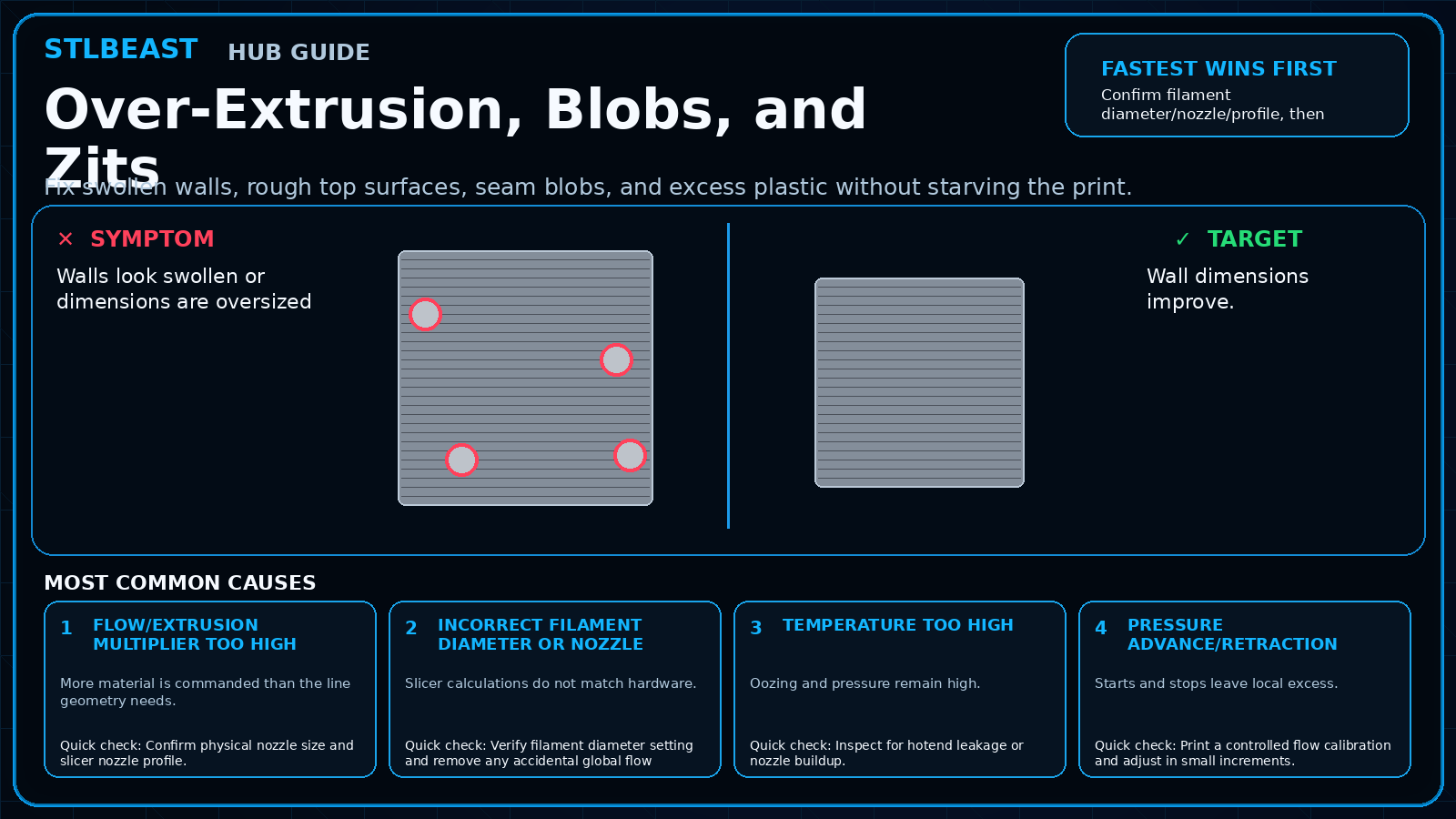
Fix holes, infill showing through, weak top skins, rough ridges, and pillowed top surfaces.
Fast answer
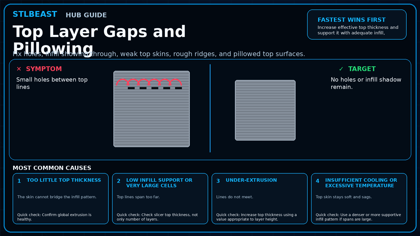
Increase effective top thickness and support it with adequate infill, cooling, and flow; do not solve every top-surface problem by adding many top layers blindly.
Use the visual comparison first, then follow the ordered checks below.
Before you change settings
Confirm the exact printer, material, nozzle or resin, slicer, and recent hardware changes.
Photograph the failure before removing the print so the evidence is not lost.
Return extreme overrides to a known profile and change one variable at a time.
Use a small calibration object or representative model section before repeating a long print.
What it looks like
Small holes between top lines
Infill pattern visible through surface
Raised pillows over infill cells
Top skin tears or sags
Most likely causes
Too little top thicknessThe skin cannot bridge the infill pattern.
Low infill support or very large cellsTop lines span too far.
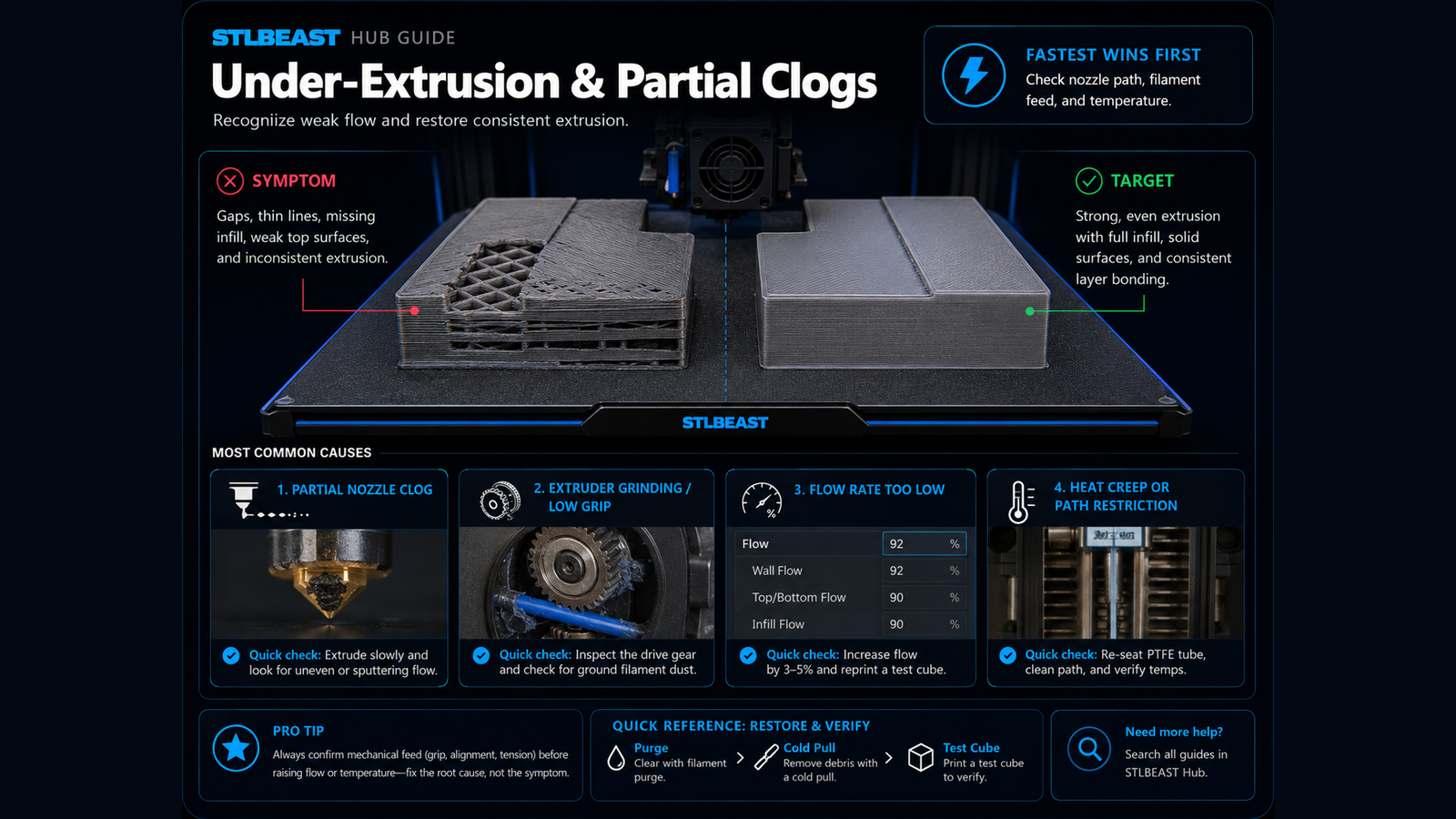
Under-extrusionLines do not meet.
Insufficient cooling or excessive temperatureTop skin stays soft and sags.
Printing top surface too fastLines do not settle consistently.
Repair sequence
Work from top to bottom. Stop when the failure is resolved, verify it with a small test, and record the successful setup.
Confirm global extrusion is healthy.
Check slicer top thickness, not only number of layers.
Increase top thickness using a value appropriate to layer height.
Use a denser or more supportive infill pattern if spans are large.
Slow top-surface speed.
Tune cooling and temperature for the material.
Use monotonic/top-surface options only after structural coverage is correct.
Safety and accuracyChange one variable at a time and keep every adjustment inside the printer, hotend, build-surface, and filament manufacturer limits.
Fast decision path
1If you see evidence of too little top thickness
The skin cannot bridge the infill pattern. Confirm it with the smallest safe test before continuing.
2If you see evidence of low infill support or very large cells
Top lines span too far. Confirm it with the smallest safe test before continuing.
3If you see evidence of under-extrusion
Lines do not meet. Confirm it with the smallest safe test before continuing.
Settings to review
Setting
How to use it
Top thickness
Think in millimetres so layer-height changes do not reduce coverage.
Top-surface speed
Use slower than infill.
Infill density/pattern
Provide reasonable support without unnecessary material.
Ironing
A finish option, not a fix for holes.
Material notes
PETG
May need balanced cooling to avoid sagging while preserving bonding.
ABS/ASA
Enclosure and lower fan may require more top support.
Printer context
Bedslinger
Check bed seating, gantry alignment, belts, eccentric wheels, and first-layer consistency across the plate.
CoreXY
Start from the official machine profile; inspect belt balance, input shaping, flow, pressure advance, and chamber conditions.
Delta
Confirm delta calibration, tower movement, belt tension, effector stability, and full-bed mapping.
Resin / SLA
Use resin-specific exposure, lift, support, temperature, wash, cure, and personal-protection procedures.
Where to look in the slicer
OrcaSlicer / Bambu Studio
Process → Quality, Strength, Speed, Support and Filament settings; use calibration tools for temperature, flow and pressure advance.
PrusaSlicer
Print Settings, Filament Settings and Printer Settings; inspect the sliced preview and layer slider before export.
Cura / Creality Print
Quality, Walls, Top/Bottom, Material, Speed, Travel, Cooling, Support and Build Plate Adhesion.
Resin slicers
Printer/resin profile, exposure, lift/retract, support contact, raft and hollow/drain settings.
How to verify the fix
No holes or infill shadow remain.
Surface is flat without balloons.
Part weight/strength is consistent.
Ironing is optional rather than required to hide defects.
Prevent it next time
Use adequate top thickness in base profiles.
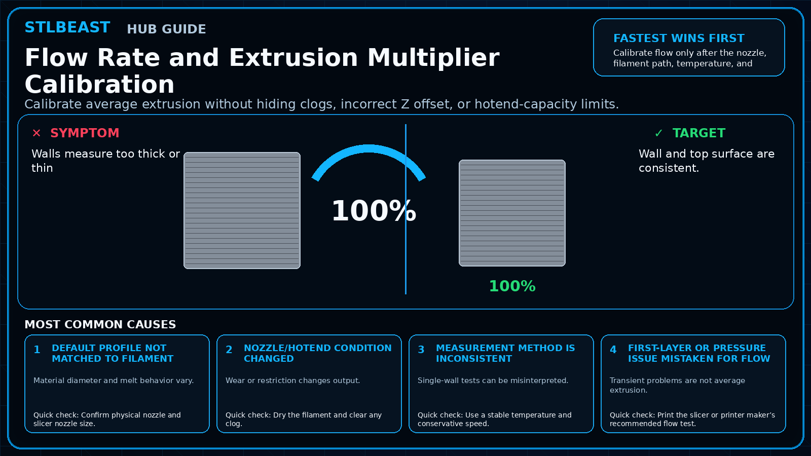
Calibrate flow.
Choose infill patterns that support broad top areas.
Avoid excessive top speed.
Printer Settings preview
Useful sample now. Full personalized profile for members.
Every visitor can use the guide and receive a practical sample. Members unlock the complete printer/material profile, exact adjustment order, copy/export controls, saved Profile Vault history, and deeper AI Doctor linkage.
Top thicknessThink in millimetres so layer-height changes do not reduce coverage.
STLBEAST ecosystemFix and learn on Hub. Build with validated files on STLBEAST.com.
Disclosure: Hub.STLBEAST is an educational resource. Some recommended-tool links may be affiliate links, including Amazon Associate links, and STLBEAST may earn from qualifying purchases at no extra cost to you.