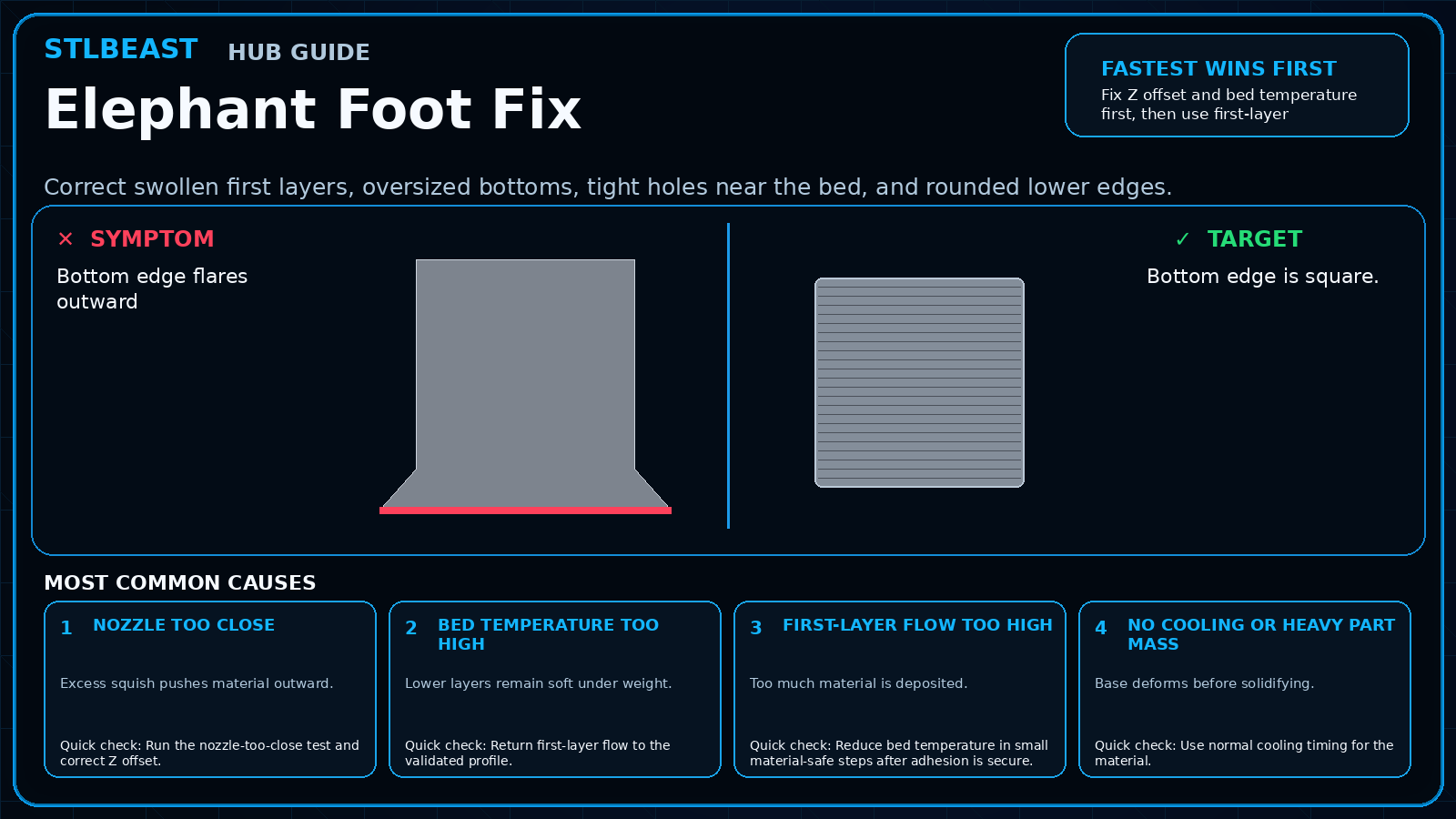
Use the visual comparison first, then follow the ordered checks below.
Before you change settings
Confirm the exact printer, material, nozzle or resin, slicer, and recent hardware changes.
Photograph the failure before removing the print so the evidence is not lost.
Return extreme overrides to a known profile and change one variable at a time.
Use a small calibration object or representative model section before repeating a long print.
What it looks like
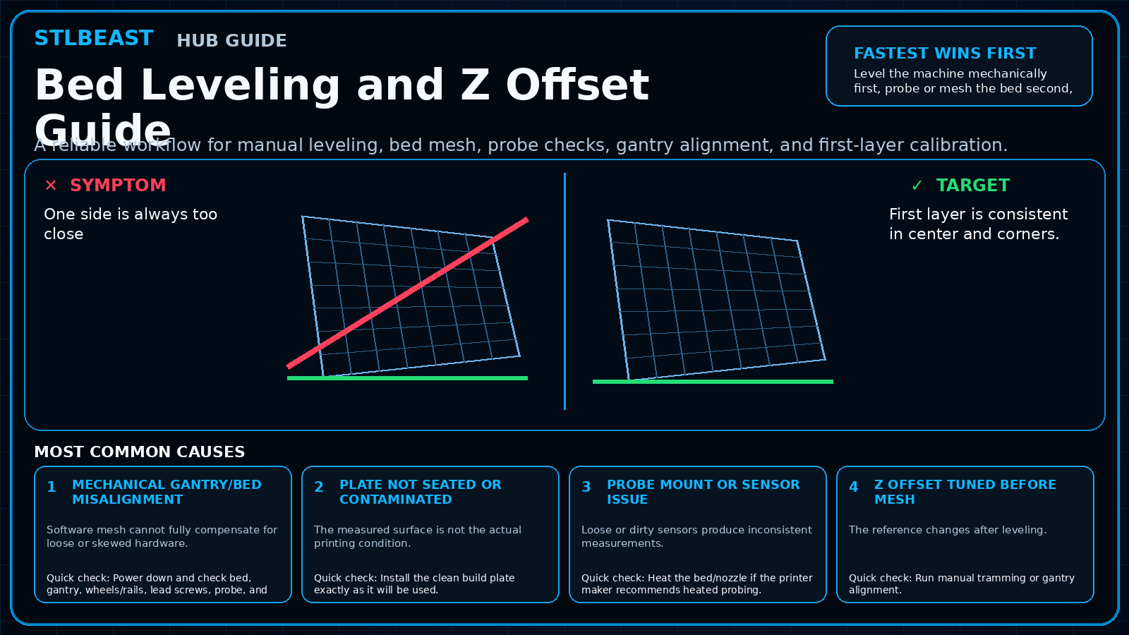
One side is always too close
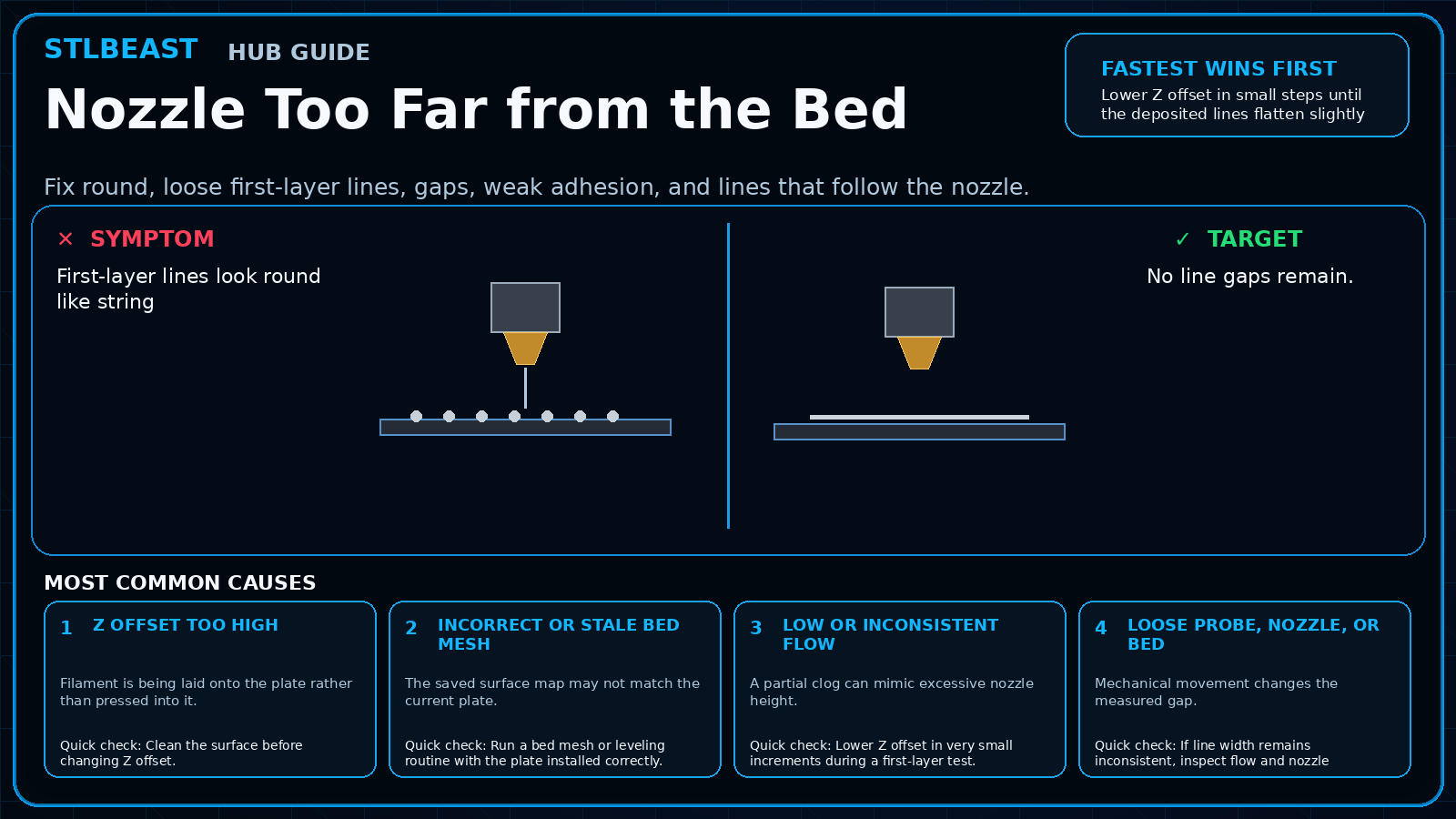
Mesh values are extreme or inconsistent
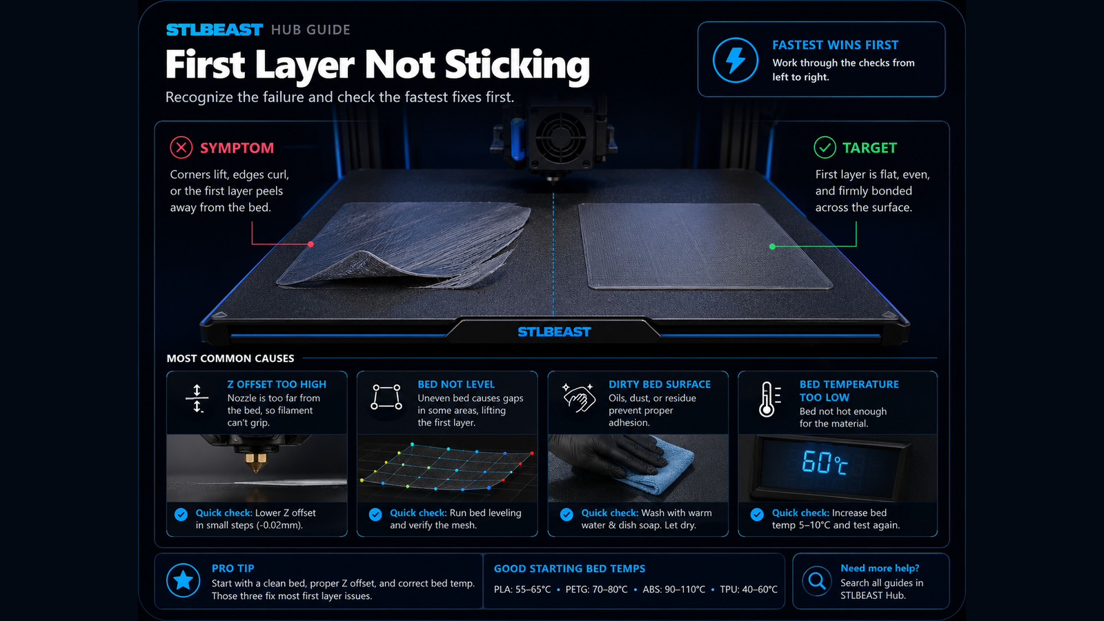
A previously good first layer suddenly fails
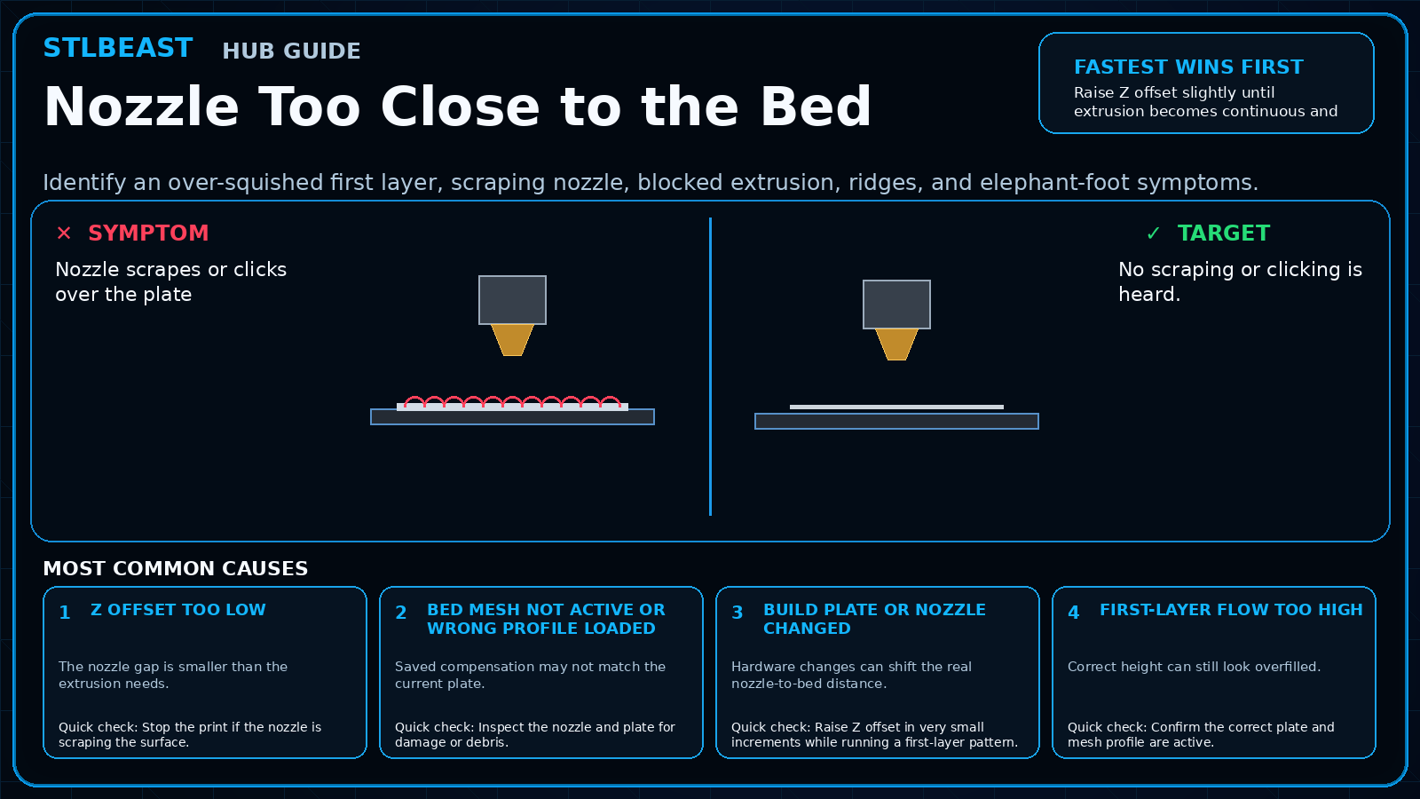
Z offset changes after maintenance
Most likely causes
Mechanical gantry/bed misalignmentSoftware mesh cannot fully compensate for loose or skewed hardware.
Plate not seated or contaminatedThe measured surface is not the actual printing condition.
Probe mount or sensor issueLoose or dirty sensors produce inconsistent measurements.
Z offset tuned before meshThe reference changes after leveling.
Nozzle residueA blob on the nozzle changes the effective probe/height reference.
Repair sequence
Work from top to bottom. Stop when the failure is resolved, verify it with a small test, and record the successful setup.
Power down and check bed, gantry, wheels/rails, lead screws, probe, and hotend for play.
Install the clean build plate exactly as it will be used.
Heat the bed/nozzle if the printer maker recommends heated probing.
Run manual tramming or gantry alignment.
Create a fresh mesh with the nozzle clean.
Load/save the correct mesh according to the printer firmware.
Tune Z offset with a large one-layer test and save the verified profile.
Safety and accuracyChange one variable at a time and keep every adjustment inside the printer, hotend, build-surface, and filament manufacturer limits.
Fast decision path
1If you see evidence of mechanical gantry/bed misalignment
Software mesh cannot fully compensate for loose or skewed hardware. Confirm it with the smallest safe test before continuing.
2If you see evidence of plate not seated or contaminated
The measured surface is not the actual printing condition. Confirm it with the smallest safe test before continuing.
3If you see evidence of probe mount or sensor issue
Loose or dirty sensors produce inconsistent measurements. Confirm it with the smallest safe test before continuing.
Settings to review
Setting
How to use it
Mesh density
Use the printer-supported mesh size; more points do not fix loose hardware.
Fade height
Use firmware defaults unless the manufacturer documents a reason to change it.
Z offset
Tune in tiny increments only after leveling is complete.
Material notes
Removable plates
Different plate thicknesses may require different Z references.
High-temperature materials
Thermal expansion can change a cold versus heated measurement.
Printer context
Bedslinger
Check bed seating, gantry alignment, belts, eccentric wheels, and first-layer consistency across the plate.
CoreXY
Start from the official machine profile; inspect belt balance, input shaping, flow, pressure advance, and chamber conditions.
Delta
Confirm delta calibration, tower movement, belt tension, effector stability, and full-bed mapping.
Resin / SLA
Use resin-specific exposure, lift, support, temperature, wash, cure, and personal-protection procedures.
Where to look in the slicer
OrcaSlicer / Bambu Studio
Process → Quality, Strength, Speed, Support and Filament settings; use calibration tools for temperature, flow and pressure advance.
PrusaSlicer
Print Settings, Filament Settings and Printer Settings; inspect the sliced preview and layer slider before export.
Cura / Creality Print
Quality, Walls, Top/Bottom, Material, Speed, Travel, Cooling, Support and Build Plate Adhesion.
Resin slicers
Printer/resin profile, exposure, lift/retract, support contact, raft and hollow/drain settings.
How to verify the fix
First layer is consistent in center and corners.
Repeated probing produces similar values.
No wheel, bed, probe, or hotend play remains.
The saved profile survives a restart and is actually loaded.
Prevent it next time
Recheck after transport or hardware work.
Clean the nozzle before probing.
Keep plate-specific profiles and labels.
Do not repeatedly compensate in software for loose hardware.
Printer Settings preview
Useful sample now. Full personalized profile for members.
Every visitor can use the guide and receive a practical sample. Members unlock the complete printer/material profile, exact adjustment order, copy/export controls, saved Profile Vault history, and deeper AI Doctor linkage.
Mesh densityUse the printer-supported mesh size; more points do not fix loose hardware.
Fade heightUse firmware defaults unless the manufacturer documents a reason to change it.
STLBEAST ecosystemFix and learn on Hub. Build with validated files on STLBEAST.com.
Disclosure: Hub.STLBEAST is an educational resource. Some recommended-tool links may be affiliate links, including Amazon Associate links, and STLBEAST may earn from qualifying purchases at no extra cost to you.